Figure shows a series LCR circuit connected to a variable
€ 36.00 · 4.9 (290) · Auf Lager

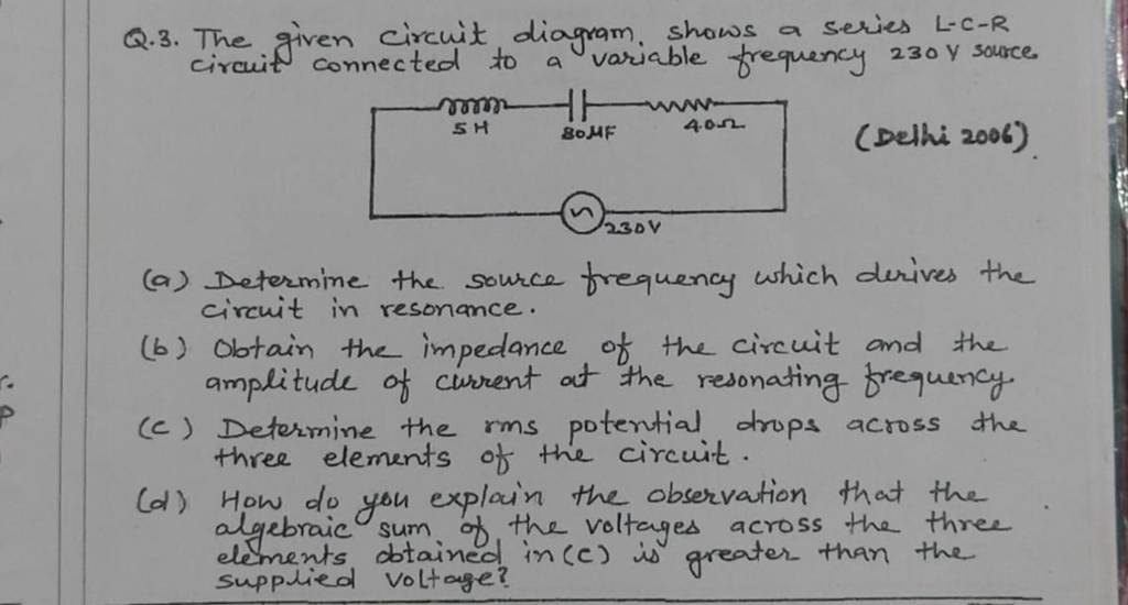
Q.3. The given circuit diagram, shows a series L−C−R circuit connected to..

Figures shows a parallel LCR circuit connected to a 200V, AC source. L=5H, `C=80muF and R=40Omega`. At resonance let `I_(1) and i_(2)` be the rs curre - Sarthaks eConnect

In a Series Lcr Circuit Connected to an Ac Source of Variable Frequency and Voltage ν = Vm Sin ωT, Draw a Plot Showing the Variation of Current (I) with Angular Frequency (

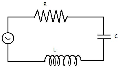
Figure shows a series LCR circuit connected to a variable frequency 230 V source. \[L = 5.0\,{\text{H}}\], \[C = 80\,\mu F\], \[R = 40\,\Omega \].(a) Determine the source frequency which drives the

The figure show a series LCR circuit with L=5.0 H, C=80mu F,R=40Omega connected to variable frequency 240 V source. Calculate (i)The angular frequency of the which driver the circuit resonance (ii) The

Figure here, shows a series L-C-R circuit connected to a variable freq

Fig 1062 shows a series LRC circuit connected to a variable frequency 230 V source L50 H C 80F R40 Determine the source frequency which drives the circuit in resonance

SOLVED: Figure 7.21 shows a series L C R circuit connected to a variable frequency 230 V source. L=5.0 H, C=80 μF, R=40 Ω. (a) Determine the source frequency which drives the
The figure shows a series LCR circuit with $L = 54H$ , $C = 80\mu F$ , $R = 40\Omega $ connected to a variable frequency $240V$ source, calculate:(A) The angular frequency